
Design & Drafting
How to Read an MEP Drawing Set (For Non-Engineers)
Owners, GCs, and project managers: a quick orientation to what's in an MEP set and how the sheets fit together.

You don't need an engineering degree to get useful information out of an MEP drawing set. Owners, general contractors, and project managers review these sets every week — approving scopes, spotting conflicts, and asking the questions that keep projects on track. Here's a practical orientation to what's in the set, how the sheets fit together, and what to look at first.
The Sheet Index Is the Map
Every set opens with a sheet index — the table of contents. Electrical sheets are usually prefixed E, mechanical M, plumbing P, and fire protection FP (sometimes F or FS). The index tells you what exists and in what order: plans first, then schedules, then details within each discipline.
If you are new to a set, read the index before anything else. It tells you the scope at a glance: how many electrical sheets (a scope with E-101 through E-601 is a full building, not a TI), whether fire protection is included, and whether there are separate demolition sheets. When a sheet is referenced on another sheet but missing from the index, that is worth a question — it may be a drafting error, or scope that was cut.
Legends and General Notes: The Rosetta Stone
Before the plans, you'll find legends (what each symbol means) and general notes (the code basis and standard requirements). When a symbol on a plan confuses you, the legend is the answer — every diamond, triangle, and letter code on the plans is defined there.
The general notes are worth a skim even for non-engineers, because they state the design basis in plain terms: which code edition the set was drawn to, the design voltages, the plumbing code, the fire protection standard. If your project is in a jurisdiction with strict amendments, the notes will say so. This is also where the drafter states assumptions — and assumptions you disagree with are cheapest to challenge now.
The Plans: Where Things Go
Plans are scaled top-down views showing where devices, ducts, pipes, fixtures, and heads go. A few things help a non-engineer read them:
- Tags connect plans to schedules. A diffuser tagged D-12 on the mechanical plan appears as D-12 in the diffuser schedule with its size and airflow. A panel labeled LP-3 on the electrical plan has a full schedule on the electrical sheets. Follow one tag through and the set stops looking like noise.
- Line weights carry meaning. Heavy lines are usually new work; screened (light gray) lines are existing; dashed lines are often demolition or future work. The legend confirms the convention for your set.
- Callouts point to details. A hexagon or circle with a number and a sheet reference ("5/E-401") means the real information lives in a detail on that sheet. Details are enlarged drawings of the tricky parts — and they are where the quality of a set shows.

Discipline by Discipline: What You're Looking At
Electrical sheets (E). Power and receptacle plans show outlets, equipment connections, and home runs back to panels. Lighting plans show fixtures and switching. The electrical system scope also includes panel schedules (tables listing every breaker, load, and spare) and the single-line diagram — the one-page map of the whole electrical distribution from the utility service down.
Mechanical sheets (M). HVAC plans show equipment, ductwork routing, diffusers, and thermostats. The equipment schedule lists every unit with its capacity and electrical characteristics. A mechanical design set covers both the air side (HVAC) and the plumbing side when both are in scope.
Plumbing sheets (P). Water, waste, vent, and gas piping plans, plus the riser diagram — a vertical schematic showing how the whole system stacks up floor to floor. The fixture schedule lists every sink, toilet, and water heater.
Fire protection sheets (FP). Sprinkler head layouts, the system riser, and hydraulic calculation summaries. If your building needs sprinklers, the sprinkler layout sheets show head coverage coordinated to the ceiling — worth a look even for non-engineers, because head locations affect ceiling aesthetics.
Schedules and Diagrams: The Tables That Matter
Schedules are tables — panels, equipment, fixtures, diffusers — listing sizes, capacities, and specifications. For a non-engineer, schedules are the fastest way to verify scope: count the panels, check the equipment tags against the equipment you bought, confirm the fixture types match what the interior designer specified.
Diagrams like the single-line and the risers show how systems connect vertically and electrically — which a flat plan cannot show. You do not need to understand every symbol; you need to confirm the diagram exists, is labeled, and agrees with the schedules. A panel on the single-line that does not appear in the schedules is a coordination error, and you just caught it without an engineering degree.
Revision Clouds: What's Changed
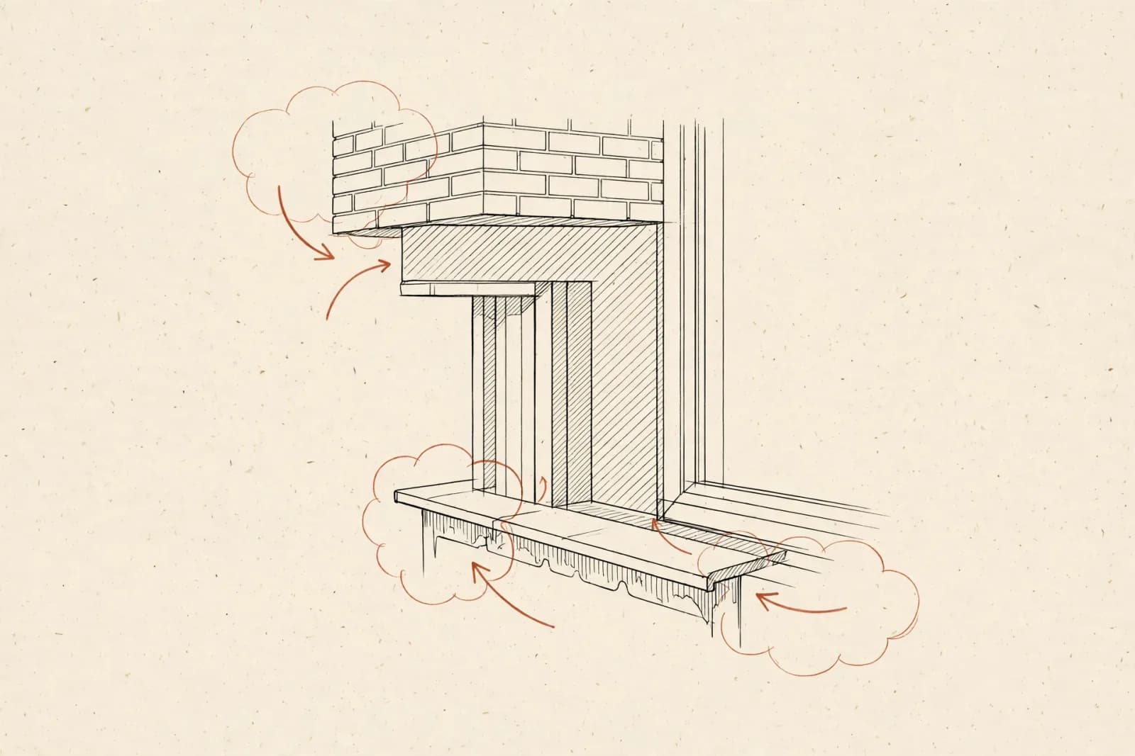
Revised sheets carry revision clouds — wavy outlines around changed areas — with a delta number (triangle with a number) tied to a revision block in the title block. When someone tells you "we addressed the review comments," the clouds show you where. Ask for a revision narrative that maps each cloud to the comment it answers; it is the fastest way to verify a resubmittal.
How It All Ties Together
A device on a plan carries a tag; that tag appears in a schedule with its specification; the schedule ties back to a diagram that shows how it is fed. Follow one item through those three views and you understand the set's logic. Then use that logic to ask good questions:
That's enough to review a set with confidence, approve scopes, and run a productive project meeting. And when the set needs to be produced in the first place — or revised after review — request a quote and we will draft it to your standard.
Need similar drawings?
Get permit-ready 2D AutoCAD drawings for your project
Send us your plans and scope — we'll come back with a fixed price and a turnaround date. No obligation.
Keep reading
Related articles
 Design & Drafting
What Makes an MEP Drawing Set Truly Permit-Ready?
Geometry alone does not get a permit issued. Here is what plan reviewers check on the sheets first — and what we build into every set we draft.
 Design & Drafting
How to Clear MEP Plan-Review Corrections Without Losing Weeks
A correction letter is not a rejection — it is a punch list. Our workflow for reading, classifying, clouding, and resubmitting corrections in a single…
 Design & Drafting
PDF to CAD Conversion: Getting Legacy Drawings Permit-Ready Again
Scanned as-builts and hand-drafted originals cannot carry a permit application. Here is how we convert legacy drawings into editable, layered,…
Get a fixed drafting quote in under 24 hours
Send us your architectural plans and scope. We'll come back with a fixed price and a turnaround date — no obligation.